Showing posts with label amplifier. Show all posts

Saturday, January 11, 2014

4 X 15 Watt Mini Power Amplifier

A lot of electronic circuits in the domain of audio amplifiers are already been published here. This circuit is a little different because it is a four channel amplifier. Each channel of this amplifier can deliver an output of 15Watts into a 4 ohm speaker. The amplifier can be operated from a single 12V DC supply and this makes it possible to use this amplifier in car audio applications too.

4 X 15 Watt Mini Power Amplifier Circuit diagram :
4X15W-amplifier-circuit Diagram

The circuit is based on the 15W BTL X 2 channel audio power amplifier IC TA8215 from Toshiba. Even though chip is specifically designed for car audio applications it can be also used for home audio applications. Two TA8215 ICs are used here in order to obtain a 4 channel amplifier system. The circuit is designed almost exactly as per the application diagram in the ICs datasheet. Pins 7 and 19 are the Vcc pins of the ICs internal integrated power amplifier stages and these pins are connected to the positive supply. Pin 9 is the Vcc pin for ICs internal preamplifier and it is also connected to the positive supply. Pins 13 and 14 are the internal power amplifiers ground pins and they are tied together and connected to the ground.
The internal preamplifier’s ground pin (pin5) is connected to the common ground through a 10 Ohm resistor which makes the input ground separated from the common ground by a resistance of 10 ohms and this improves the noise rejection. The 100uF capacitor works as a power supply de-coupler. The resistor networks connected to the output lines of each amplifier improves the high frequency stability. The variable resistors (R3, R4, R12 and R13) works as the volume controller for the corresponding channels.

Notes :
  • Assembling the circuit on a good quality PCB is a must for obtaining optimum sound quality.
  • Use 12V DC for powering the circuit.
  • The ICs must be fitted with adequately sized heat sinks.
  • R3, R4, R12 and R13 serves as volume controllers.
  • K1 to K4 can be 4 Ohm, 20W speakers.
  • This amplifier circuit can be used in a variety of applications such as car audio systems, home theater systems, personal audio systems, public address systems etc.
Source : http://www.ecircuitslab.com/2012/08/4-x-15-watt-mini-power-amplifier.html
Continue Reading..

Friday, January 10, 2014

Guitar Amplifier

10W Old-Style ultra-compact Combo, Two inputs - Overdrive - Treble-enhancement
The aim of this design was to reproduce a Combo amplifier of the type very common in the sixties and the seventies of the past century. It is well suited as a guitar amplifier but it will do a good job with any kind of electronic musical instrument or microphone. 5W power output was a common feature of these widespread devices due to the general adoption of a class A single-tube output stage (see the Vox AC-4 model). Furthermore, nowadays we can do without the old-fashioned Vib-Trem feature frequently included in those designs. The present circuit can deliver 10W of output power when driving an 8 Ohm load, or about 18W @ 4 Ohm. It also features a two-FET preamplifier, two inputs with different sensitivity, a treble-cut control and an optional switch allowing overdrive or powerful treble-enhancement.

Guitar Amplifier Circuit Diagram

Guitar Amplifier Circuit Diagram

Parts:
P1______________4K7 Linear Potentiometer
P2_____________10K Log. Potentiometer
R1,R2__________68K 1/4W Resistors
R3____________220K 1/4W Resistor
R4,R6,R11_______4K7 1/4W Resistors
R5_____________27K 1/4W Resistor
R7______________1K 1/4W Resistor
R8______________3K3 1/2W Resistor
R9______________2K 1/2W Trimmer Cermet
R10___________470R 1/4W Resistor
R12_____________1K5 1/4W Resistor
R13___________470K 1/4W Resistor
R14____________33K 1/4W Resistor
C1____________100pF 63V Ceramic Capacitor
C2____________100nF 63V Polyester Capacitor
C3____________470µF 35V Electrolytic Capacitor
C4____________220nF 63V Polyester Capacitor (Optional, see Notes)
C5_____________47µF 25V Electrolytic Capacitor (Optional, see Notes)
C6______________1µF 63V Polyester Capacitor
C7,C8,C9,C10___47µF 25V Electrolytic Capacitors
C11____________47pF 63V Ceramic Capacitor
C12__________1000µF 35V Electrolytic Capacitor
C13__________2200µF 35V Electrolytic Capacitor
D1_____________5mm. Red LED
D2,D3________1N4004 400V 1A Diodes
Q1,Q2________2N3819 General-purpose N-Channel FETs
Q3____________BC182 50V 200mA NPN Transistor
Q4____________BD135 45V 1.5A NPN Transistor (See Notes)
Q5____________BDX53A 60V 8A NPN Darlington Transistor
Q6____________BDX54A 60V 8A PNP Darlington Transistor
J1,J2________6.3mm. Mono Jack sockets
SW1____________1 pole 3 ways rotary switch (Optional, see Notes)
SW2____________SPST Mains switch
F1_____________1.6A Fuse with socket
T1_____________220V Primary, 48V Center-tapped Secondary 20 to 30VA Mains transformer
PL1____________Male Mains plug
SPKR___________One or more speakers wired in series or in parallel, Total resulting impedance: 8 or 4 Ohm, Minimum power handling: 20W
Notes:
  • SW1 and related capacitors C4 & C5 are optional.
  • When SW1 slider is connected to C5 the overdrive feature is enabled.
  • When SW1 slider is connected to C4 the treble-enhancer is enabled.
  • C4 value can be varied from 100nF to 470nF to suit your treble-enhancement preferences.
  • In all cases where Darlington transistors are used as the output devices it is essential that the sensing transistor (Q4) should be in as close thermal contact with the output transistors as possible. Therefore a TO126-case transistor type was chosen for easy bolting on the heatsink, very close to the output pair.
  • To set quiescent current, remove temporarily the Fuse F1 and insert the probes of an Avo-meter in the two leads of the fuse holder.
  • Set the volume control to the minimum and Trimmer R9 to its minimum resistance.
  • Power-on the circuit and adjust R9 to read a current drawing of about 25 to 30mA.
  • Wait about 15 minutes, watch if the current is varying and readjust if necessary.
Technical data are quite impressive for so simple a design:
Sensitivity:
30mV input for 10W output
Frequency response:
40 to 20KHz -1dB
Total harmonic distortion @ 1KHz and 10KHz, 8 Ohm load:
below 0.05% @ 1W, 0.08% @ 3.5W, 0.15% at the onset of clipping (about 10W).

Source :  http://www.ecircuitslab.com/2011/05/guitar-amplifier-circuit-diagram.html
Continue Reading..

Friday, December 27, 2013

LA4440 Amplifier Circuit

LA4440 is a dual channel audio amplifier IC. It can be used in two modes; one is Stereo amplifier and another Bridge amplifier mode. The LA4440 is a monolithic linear IC from Sanyo. Here I give the both circuit mode of amplifier using IC LA4440.

Features of IC LA4440

  • It has 46dB of ripple rejection
  • Low distortion
  • Good channel separation
  • Thermal protector
  • Overvoltage protector
  • Surge voltage protector

LA4440 Stereo Amplifier Circuit

When the IC LA4440 is Stereo mode in the circuit, its output power is 6w+6w. In stereo mode use two pieces speaker of 2Ωto8Ω.
In the stereo amplifier configuration given below, C11 and C12 are output capacitor. But i ignore them from the circuit of bridge amplifier.

Stereo Amplifier Circuit using IC LA4440
Fig-1: LA4440 Stereo Amplifier Circuit Diagram

LA4440 Bridge Amplifier Circuit

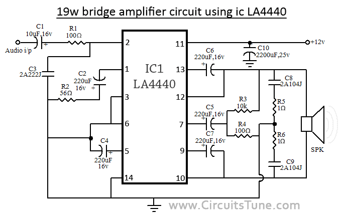
When the IC LA4440 is in Bridge mode in the circuit, its output power is 19w. In bridge mode use 4Ω-8Ω speaker. If you want stereo output(19w+19w) in bridge mode then use two copies of amplifier circuit of given below. Resistor R3&R4 is to adjust the voltage gain and for making input signal of inverting amplifier.

Bridge Amplifier Circuit using  IC LA4440
Fig-2: LA4440 Bridge Amplifier Circuit Diagram

Circuit description for both, stereo and bridge amplifier mode


C10 is filter capacitor used to reduce the ripple of supply voltage. Don’t decrease the value of capacitor C6&C7 less than 100uF, 10v, it may causes of the output at low frequencies goes lower. The pin-6 of LA4440 amplifier circuit  is audio input pin; it used in stereo amplifier mode but in bridge mode it is grounded. C8&C9 are polyester film capacitor used to preventing oscillation, and R1&R2 used for the same reason as filter resistor. Though the maximum supply voltage for both circuit of amplifier is 18V but we recommend to use a 12V,3A power supply. Use a good quality heat sink with LA4440.

I think here you see little comparison between stereo and bridge amplifier of LA4440. If you want to make this amplifier project, then I recommend you the bridge one. I think it is ideal for a beginner. And I love its wattage rather than Stereo mode. There is also a possibilities as I say, make two copies of circuit of bridge amplifier for stereo, it will give you 19w+19w of audio power output.
Continue Reading..

Sunday, October 6, 2013

Speach Amplifier Circuit Diagram

This circuit is intended to be placed in the same box containing the loudspeaker, forming a compact microphone amplifier primarily intended for speech reinforcement. A device of this kind is particularly suited to teachers, lecturers, tourists guides, hostesses and anyone speaking in crowded, noisy environment.

The circuits heart is formed by the TDA7052 Audio power amplifier IC, delivering a maximum output of 1.2W @ 6V supply. An external microphone must be plugged into J1, its signal being amplified by Q1 and fed to IC1. R1 acts as a volume control and C3 tailors the upper audio frequency band, mainly to reduce the microphone possibility of picking-up the loudspeaker output, causing a very undesirable and loud "howl", i.e. the well known Larsen effect. Therefore, C3 value can be varied in the 4n7 - 22nF range to ensure the best compromise from speech tone quality and minimum Larsen effect occurrence. Dynamic or electrets microphone is warmly recommended. It has a useful feature that can be used to momentarily mute the microphone by connecting SW1 shown in diagram.

Circuit Diagram:

Speech Amplifier Circuit Diaram Speach Amplifier Circuit Diagram

Parts Description
R1 22K
R2 1M
R3 15K
R4 470R
R5 47K
R6 4.7K
C1 100nF-63V
C2 100nF-63V
C3 100nF-63V
C4 10nF-63V
C5 220uF-25V
C6 10uF-25V
Q1 BC547
IC1 TDA7052 B1
J1 Mono Jack Socket
B1 6V Battery
SW1 SPST Slider Switch
SW2 SPST Toggle Switch

Notes:

  • Please note that hands-free, uni-directional headset or ear clip microphone types are very well suited for this device, as also are Clip-on Lavaliere or Lapel microphones.
  • If a small electrets capsule is used for the microphone, R5, R6 and C6 must be added to the circuit to provide power supply.
  • Choose a loudspeaker as large as possible, in order to increase circuit performance.
  • You can use also two 4 Ohm loudspeakers wired in series or two 8 Ohm types wired in parallel in order to obtain better results.
  • The box containing the amplifier and loudspeaker(s) can be fitted out with a belt and carried like a shoulder-bag or, if you build a smaller unit, it can be used as a Pick & Go Belt Clip Speaker.

Source : www.redcircuits.com

Continue Reading..

Saturday, April 13, 2013

Build 10 Watt Audio Power Amplifier Circuit

10W Audio Power Amplifier Circuit

10W PA.The 10 watts power amplifier circuit with the aid of transistor describe right here is an audio amplifier with output power of 10W.Used as a low frequency type AB Amplifier. Transistor has high output present and very low distortion.This 10W audio amplifier circuit diagram using Transistor is good for small room or car audio device.This circuit is a general-purpose 10W audio amplifier for moderate-power PA or modulator use in an AM transmitter.

With better voltages and a change in bias resistors,up to 30 W may additionally be obtained.
Continue Reading..

Friday, April 12, 2013

60W POWER AMPLIFIER CLASS B CIRCUIT DIAGRAM

60W POWER AMPLIFIER CLASS B CIRCUIT DIAGRAM

Capacitor C1 regulates the low frequencies (bass), as the capacitance grows, the low frequencies are getting louder. Capacitor C2 regulates the higher frequencies (treble), as the capacitance grows, the higher frequencies are getting quieter.

This is a class B amplifier, this means, that a current must flow through the end transistors, even if there is no signal on the input. This current can be regulated with the 500 Ohm trimmer resistor. As this current increases, the sound of the amplifier is better, but output transistors are dispatching more heat. If the current is decreased, the transistors are dispatching less heat, but the sound quality is decreased.
Continue Reading..

Wednesday, April 10, 2013

TDA2004 stereo bridge audio amplifier

tda2004 bridge
Most of the lovers, especially in audio electronics, it will never escape from this one component of the IC TDA2004. Because these components are very easy to get and the price is also quite cheap. Amplfiier audio series was also quite easy to make because the circuit is not too complicated, and one ic also already has 2 outputs and inputs.

Not only that, the audio is processed from the IC is also well qualified, many power power branded car, using it as an amplifier ic. Nothing mistake this ic tried to make an audio amplifier. For the circuit scheme can be seen below.
schematic power amplifier with TDA2004
with this amplifier circuit you can easily enhance your audio levels, from your stereo walkman, Ipod, tuner, MP3 player or MP4, the portable receiver, laptops or PCs


Continue Reading..

Tuesday, April 9, 2013

10W audio power amplifier with bass boost


As the amplifier circuit also uses a number of frequencies to drive the loudspeaker, the bass frequencies will be reduced. Therefore need to be plugged the bass-boost control at fedback loop amplifier, this is done to overcome the decline in quality.


Graph bass can reach a maximum at +16.4 dB @ 50Hz.
This circuit can be connected directly to the CD player, tuner, and tape recorders. Q3 and Q4 must be in pairs with a heatsink.

Adjust the volume control at minimum position and R3 with a minimum value of resistance as well. try enabling circuit R3 da set up to read the flow of about 20 to 25mA. Wait for 15 minutes, connect the ground at J1, P1, C2, C4 C3dan. Connect also C9 at the output ground.


For his series of power supply you can use the following scheme that fits perfectly with this amplifier.


Continue Reading..

Monday, April 8, 2013

Dual Input Far Field Noise Suppression Microphone Amplifier Circuit


This is a circuit diagram for microphone amplifier. This circuit is using LMV1090 as based op amp signal in the circuit. This is the figure of the circuit;


The LMV1090 is a fully analog dual differential input, differential output, microphone array amplifier designed to reduce background acoustic noise, while delivering superb speech clarity in voice communication applications. The LMV1090 preserves near-field voice signals within 4cm of the microphones while rejecting far-field acoustic noise greater than 50cm from the microphones. Up to 20dB of far-field rejection is possible in a properly configured and using ±0.5dB matched microphones. [Schematic circuit source: National Semiconductor Notes].
Continue Reading..

5000W High Power Audio Amplifier

The High Power Amplifier has great advantages are 5000W ultra-light, high-power audio amplifier, without switching-mode power supply. This ambit is of an 2 x 2,500W RMS Stereo amplifier, super-light and after switching-mode ability supply. The ambit aloof shows a channel, and the ability accumulation that it assists to the two channels. The audio ambit should be duplicated, but the ability accumulation assists to the two channels after problems.
5000W High Power Amplifier Audio Circuits
Click To view larger | 5000W High Power Amplifier Audio Circuits Diagrams

A adapted affliction should be destined to the careful agent of the audio line, that should be of audio-high-quality, of the blazon acclimated in microphone pre amps ascribe line. The accomplished accumulation (2 channels) of 5,000W RMS it should not counterbalance added than 32 lbs, already central of an adapted brownish box.

WARNING:
This ambit is alone for abecedarian use. It contains not-isolated genitalia of the electric AC net and it can be actual dangerous. The access for the speakers are not abandoned of the calm AC net and it requests added care. This action seeks to acting a accepted ability accumulation with abundant weight and amount reduction, after necessarily to use a switching-mode ability supply.

This action cannot be accustomed in some countries for commercial-use. The columnist doesn’t accept any albatross for the anatomy as that ambit it will be applied.
Continue Reading..

Saturday, April 6, 2013

Tube Power Amplifier 35W Push Pull

Tube Power Amplifier 35W Push Pull is made using a tube and eventually compiled configuration push-pull amplifier. Tube Power Amplifier 35W Push Pull tube til it using EL-34 as the amplifier end.
In the power amplifier that is made with a tube at a glance looks simple because the use of active components that are not complex. It should be noted that the use of tubes in Tube Power Amplifier 35W Push Pull require a high voltage supply, therefore in the process of making and finishing must be careful of high voltage and radiation. Detailed series of Tube Power Amplifier 35W Push Pull can be seen in the following figure.

Tube Power Amplifier Series 35W Push Pull

Sign Components Tube Power Amplifier 35W Push Pull
R1 = 470K 0.5 W
R2-5 = 2K2 0.5W
R3 = 150K 0.5W
R4 = 220K 0.5W
R6-10 = 56K 0.5W
R7 = 3.9K 0.5W
R8 = 220R 0.5W
R9 = 1M 0.5W
R11 = 39K 1W
R12-23 = 180K 0.5W
R13-21 = 820K 0.5W
R14-22 = 5K6 0.5W
R15-20 = 680K 0.5W
R16-19 = 100K 0.5W
R17-18 = 3K3 1W
R24 = 470R 2W
TR1-2 = 470R 1W Variable (adj. 270Ω)
C1-3-6-7 = 0.1uf 630V
C2 = 220pF 600v
C4-5 = 16uF 550V
C8-9 = 0.1uF 630V
C10-14 = 0.47uF 630V
C11-13 = 25uF 40V
V1 = E80CC
V2 = E80CC
V3-4 = EL34
Rectifier tube = Z2C
Audio Transformer for T1 = 2x EL34 Push Pull
Power amplifier with tubes often become the choice for a small slewrate so that the resulting audio quality is guaranteed. Tube Power Amplifier 35W in the circuit that is required to supply a high DC voltage is +220 VDC ddengan order to work properly.
Continue Reading..

Friday, April 5, 2013

Stereo Headphone Amplifier

Stereo Headphone Amplifier circuit uses DC voltage source 9Volt. As the name suggests this headphone amplifier circuit has inpur stereo and output to power about 50mW at 32 Ohm load. The series of "Stereo Headphone Amplifier" It uses mini-amplifier IC NE5534. Because of this NE5534 IC didalamanya there are 2 pieces mini amplifier then simply use 1 piece of IC NE5534 to Stereo Amplifier aHeadphone this. Stereo Headphone Amplifier series has this capability and low distortion, low noise. Stereo Headphone Amplifier circuit has a strengthening of 3.5 with 3.6 Vpp at 32 Ohm load.


Stereo Headphone Amplifier

Component Stereo Headphone Amplifier
P1 = 22K
R1 = 18K
R2 = 68K
R3 = 68K
R4 = 68K
R5 = 18K
R6 = 68K
C1 = 4.7uF/25v
C2 = 4.7uF/25v
C3 = 22pF
C4 = 220uF/25v
C5 = 220uF/25v
C6 = 4.7uF/25v
C7 = 22pF
C8 = 220uF/25v
J1 = 3.5mm Stereo Jack
B1 = 9V Alkaline Battery
IC1 = NE5532 or NE5534
SW1 = SPST Toggle Switch
Continue Reading..

Thursday, April 4, 2013

High Quality Mosfet Amplifier

High Quality Mosfet Power Amplifier . These amplifiers circuit can be used for virtually any application that requires high performance, low use Noise, distortion and excellent sound quality. Examples would be subwoofer amplifier should FOH stage Amplifiers, surround a canal a very powerful sound amplifier, etc. The 400W MOSFET-amplifier has four key stages of amplification. We are looking to start any Phase appropriate detail.

Schematics Diagram 400W MOSFET Amplifier


As the name suggests All Q ,C and ZD the Bias and buffer phases. Its main goal is to provide a stable MOSFET Gates and offset voltage and the voltage buffer amplifier stage of the High Resource capacity. What would have without the phase response and the effect Slew rate is indeed very bad. The flip side of the coin is not the extra step Introduction of an additional dominant pole in the amplifier feedback loop.

Also to what the name suggests this stage converts the voltage developed in the VAS and provides all the amps required to drive at 8 or 4 ohms. 2-ohm loads are possible for several minutes at a time. In fact, I have tested more than 1600 1kW amplifier Watts RMS at 2 ohms. But that would not be recommended as a long-term exposure at all. If it is higher than the figures of the STI-amp. Power to the AV amplifier 800 The components of the power for this amplifier are as follows, and are favored A channel or a power module alone. 1 toroidal transformer with a rating of 1kVA. Primary windings are made to fit.
source:[link]
Continue Reading..

2 X 50W ICs amplifier with STK4191

STK4191 amplifier schematics
The above is a stereo amplifier circuit based on IC STK4191 with 2 X 50Watt output power 8 ohm impedance. And besides that you can use some of the IC can also be applied in this series include the STK4101, 4111, 4121, 5131, 4141, 4151, 5161, 4171, 4181, and 4191. Required supply voltage from 12 Volt to 35 Volt DC.
Part List :
R1 = 22K
R2 = 22K
R3 = 560R
R4 = 56K
R5 = 1K
R6 = 1K
R7 = 100R
R8 =  2K
R9 = 2K
R10 = 4.7R
R11 = 2K2
R12 = 2K2
R13 = 4.7R
R14 = 100R
R15 = 56K
R16 = 560R
C1 = 0.1uF
C2 = 0.1uF
C3 = 100uF
C4 = 100uF
C5 = 100uF
C6 = 0.1uF
C7 = 47uF
C8 = 47uF
C9 = 0.1uF
C10 = 100uF
C11 = 100uF
U1 = STK4191
Continue Reading..

6 5Watt Amplifier circuit with MPC571C

This circuit requires voltage +, -, and ground to provide power supply on this amplifier in order to work. And requires a minimum voltage 15 volts DC. This amplifier circuit uses IC MPC571C, which has a 6.5 Watt output degan 8 ohm impedance.
6.5Watt Amplifier circuit with MPC571C
Continue Reading..

Wednesday, April 3, 2013

Stereo Amplifier with Voltage Regulators

A simple stereo audio amplifier is built around two 7905 negative-voltage regulators (IC1 and IC2) and a few discrete components. The circuit will also work with other 79XX regulators if appropriate power supply is used. Regulator IC 7905 works as an amplifier for the voltages applied to common pin2 (Ground or GND). Also check the LM317 audio amplifier, another interesting circuit.
The minimal voltage drop over the standard 7905 is around 2V and it depends on the output current. Feedback resistors in the IC set the gain of the channel internally. The amplifier is a class-A audio amplifier. The minimal applicable value of R3 for the regulator 7905 is 8.2 to 10 ohms per 5W.

1W Stereo Amplifier with Voltage Regulators Circuit Diagram

A simple Stereo Amplifier with Voltage Regulators

If the required output current for LS1 is below 100 mA, the value of resistor R3 can be 33 to 51 ohms per watt. The circuit works with any load resistance (R3 in parallel with LS1 as the load) under the condition that the regulator is not overloaded with current and power dissipation. However, it is preferable to use a loudspeaker with a high resistance (8 ohms, 16 ohms or more). The amplifier works well with low-impedance headphones having a resistance of 24 to 32 ohms. The voltage difference between the ground pin of 7905 and the output pin is fixed internally.
S2 is the on/off switch. Switch S1 is for mono/stereo selection. When switch S1 is closed, the amplifier works as a two-way mono amplifier. If S1 is open, the amplifier works as a stereo amplifier. If no input signal is applied, the DC voltage on the output of the regulator 7905 should be around –5V, which depends to some extent on the value of VR1. The maximum output current of 7905 can be up to 1A and the maximum power dissipation is up to 15W. Mount the regulator IC 7905 on a heat-sink with thermal resistance below 15°C/W.
Source:  http://www.ecircuitslab.com/2012/08/a-simple-stereo-amplifier-with-voltage.html
Continue Reading..

Monday, April 1, 2013

Mini Portable Guitar Amplifier

Can be fitted into a packet of cigarettes, Also suitable as Fuzz-box
This small amplifier was intended to be used in conjunction with an electric guitar to do some low power monitoring, mainly for practice, either via an incorporated small loudspeaker or headphones. The complete circuit, loudspeaker, batteries, input and output jacks can be encased in a small box having the dimensions of a packet of cigarettes, or it could be fitted also into a real packet of cigarettes like some ready-made units available on the market.
This design can be used in three different ways:
  • Loudspeaker amplifier: when powered by a 9V alkaline battery it can deliver about 1.5W peak output power to the incorporated loudspeaker.
  • Headphone amplifier or low power loudspeaker amplifier: when powered by a 3V battery (2x1.5V cells) it can drive any headphone set type at a satisfactory output power level or deliver to the incorporated loudspeaker about 60mW of output power. This configuration is useful for saving battery costs.
  • Fuzz-box: when powered by a 3V battery (2x1.5V cells) and having its output connected to a guitar amplifier input the circuit will behave as a good Fuzz-box, showing an output square wave with marked rounded corners, typical of valve-circuits output when driven into saturation.
Mini Guitar Amplifier Circuit Diagram
Mini Portable Guitar Amplifier

Parts:
R1__________22K 1/4W Resistor
C1__________10µF 25V Electrolytic Capacitor
C2__________100nF 63V Polyester or Ceramic Capacitor
C3__________220µF 25V Electrolytic Capacitor
IC1_________TDA7052 Audio power amplifier IC
J1,J2_______6.3mm Stereo Jack sockets (switched)
SPKR_______8 Ohm Loudspeaker (See Notes)
B1_________9V PP3 Battery or 3V Battery (2 x 1.5V AA, AAA Cells in series etc.)
Clip for PP3 Battery or socket for 2 x 1.5V AA or AAA Cells

Notes:
  • For the sake of simplicity and compactness, this unit employs a dual bridge IC amplifier and a few other parts. For the same reason no volume or tone controls are provided as it is supposed that the controls already existing on the electric guitar will serve satisfactorily to the purpose.
  • No power switch is used: the battery voltage will be applied to the circuit when the input plug will be inserted in the input jack socket J1. For this purpose be sure that the input plug is a common 1/4 inch guitar mono jack plug and J1 is a 1/4 inch stereo jack socket.
  • The output jack socket J2 must be a switched stereo type. The changeover switching is arranged in such a way that, when a common headphones stereo jack plug is inserted into the socket, the loudspeaker will be disabled and the mono output signal will drive both the headsets in series, allowing full headphone reproduction. When used as a Fuzz-box output, a mono jack plug must be inserted into J2.
  • If the amplifier is intended to be encased in a packet of cigarettes, standard loudspeaker diameter should be 57 or 50mm.
Technical data:
Max output power: 1.5W @ 9V supply - 8 Ohm load; 60mW @ 3V supply - 8 Ohm load
Frequency response: Flat from 20Hz to 20kHz
Total harmonic distortion @ 100mW output: 0.2%
Max input voltage @ 3V supply: 8mV RMS
Minimum input voltage for Fuzz-box operation: 18mV RMS @ 3V supply
Current consumption @ 400mW and 9V supply: 200mA
Current consumption @ 250mW and 9V supply: 150mA
Current consumption @ 60mW and 3V supply: 80mA
Quiescent current consumption: 6mA @ 9V, 4mA @ 3V supply
Fuzz-box current consumption: 3mA @ 3V supply

Source :  http://www.ecircuitslab.com/2011/06/mini-portable-guitar-amplifier_08.html
Continue Reading..