Showing posts with label with. Show all posts

Monday, September 23, 2013

Battery Switch With Low Dropout Regulator

In the form of the LT1579 Linear Technology (www.linear-tech.com) has produced a practical battery switch with an integrated low-dropout regulator. In contrast to previous devices no diodes are required. The circuit is available in a 3.3 V version (LT1579CS8-3.3) and in a 5 V version (LT1579CS8-5), both in SO8 SMD packages. There is also an adjustable version and versions in an SO16 package which offer a greater range of control and drive signals. The main battery, whose terminal voltage must be at least 0.4 V higher than the desired output voltage, is connected to pin IN1. The backup battery is connected to pin IN2. The regulated output OUT can deliver a current of up to 300 mA. The LDO regulator part of the IC includes a pass transistor for the main input voltage IN1 and another for the backup battery on IN2.

Battery_Switch_With_LDO_Regulator_Circuit_Diagramw

The IC will switch over to the backup battery when it detects that the pass transistor for the main voltage input is in danger of no longer being able to maintain the required output voltage. The device then smoothly switches over to the backup battery. The open-drain status output BACKUP goes low to indicate when this has occurred. When neither battery is able to maintain the output voltage at the desired level the open-drain output DROPOUT goes low. The LT1579 can operate with input voltages of up to +20 V from the batteries. The regulator output OUT is short-circuit proof. The shutdown input switches off the output; if this feature is not required, the input can simply be left open.

Continue Reading..

Tuesday, September 10, 2013

An LCD Clock Kit Suitable for Beginners with Open Source Arduino Firmware

Simpleclock is an easy to assemble attractive 4-digit 7-segment LED display clock with temperature and alarm function. It is available in three display colors: Red, Blue and White. It comes as a kit of through-the-hole parts and can be soldered by any person with basic soldering experience. An attractive acrylic stand is included.

Continue Reading..

Tuesday, April 9, 2013

10W audio power amplifier with bass boost


As the amplifier circuit also uses a number of frequencies to drive the loudspeaker, the bass frequencies will be reduced. Therefore need to be plugged the bass-boost control at fedback loop amplifier, this is done to overcome the decline in quality.


Graph bass can reach a maximum at +16.4 dB @ 50Hz.
This circuit can be connected directly to the CD player, tuner, and tape recorders. Q3 and Q4 must be in pairs with a heatsink.

Adjust the volume control at minimum position and R3 with a minimum value of resistance as well. try enabling circuit R3 da set up to read the flow of about 20 to 25mA. Wait for 15 minutes, connect the ground at J1, P1, C2, C4 C3dan. Connect also C9 at the output ground.


For his series of power supply you can use the following scheme that fits perfectly with this amplifier.


Continue Reading..

Monday, April 8, 2013

How to Make a Bicycle Horn with Ringtone


The old fashioned mechanical bicycle horns are slowly getting discarded now and the folks are more interested to replace them with the musical horns imitating well as phone ringtones. One such project is discussed in this article. The circuit is very easy to build as it incorporates just a couple of active parts and a few other passive parts. The circuit can be operated with 3 volts DC through two penlight AAA size.


Electronic hobbyists who also own a bicycle will love this project. The proposed idea will help you to get rid of your old mechanical bicycle horn with a brand new loud electronic horn. Its a homemade project - another aspect that will amuse the young folks. Lets learn the whole procedure here.

Circuit Description and Construction Clues


Referring to the figure we can see how simple it is to construct the proposed circuit as it utilizes very few electronic parts. The transistor T1 is an ordinary general purpose transistor, the well known 8050. An 8050 is more powerful than the usual BC547 types and is able to handle current up to 150 mA comfortably. The transistor also owns the property of having greater hFE levels than other similar types of transistor resulting in better amplification of the music, and yes it is there basically to amplify the music source.
The music source here is the incredible IC UM66 which has an embedded piece of music “written” inside it. It just needs a supply voltage of 3 V (not to exceed) to get going. The pin-outs are also pretty simple to understand. The left one is the negative, center one is the positive and the right leg is the output – simple isn’t that?
Once the relevant supply terminals of the UM66 are assigned to their posts, it starts “singing” right away through its output pin. However, this audio level is very low and needs to be amplified before feeding it to the step-up coil. This is done by T1 as explained above and the amplified signal is sent to the coil.

The coil used here actually acts as a step-up transformer and is primarily used for stepping up the amplified music fluctuations from the transistor T1. The coil just like any other transformer as a primary and a secondary sections, however the sections are not isolated, rather are wound as a single winding with the center tap appropriately pulled out at the relevant calculated step.

The primary and the secondary winding leads are identified by measuring the corresponding resistances using a multi-tester. The leads which show lower resistance is the primary winding, and the one which shows relatively higher value is the secondary winding.

Normally the primary section will indicate a value of around 22 ohms while the secondary shows a value of around 160 ohms. The common lead across the measurements is the center tap and goes to the positive supply.
The piezo plate which is responsible for the actual reproduction of the sound is connected across the secondary winding directly. The terminals of the piezo from the central white area and the outer metal rim, both the areas are solderable, however soldering the connection over the inner circle needs great care, make sure the solder tip is lifted as soon as the solder spot is made, otherwise the white ceramic coating will immediately get burnt reducing some efficiency of the device. Another aspect with the piezo element is its installation or the fixing method.

The fixing is done over a plastic dish or cap having some depth (around 5 mm) and an inner elevated step of about 1.5 mm in height and 1 mm in width, covering the inner bottom edge of the cap (see fig). The inner diameter of the cap is such that the piezo just brushes inside the cap and settles over the elevated step. And it’s exactly how the piezo is placed and stuck inside the cap (see figure).

The sticking can be done by some good quality synthetic rubber based glue (as used for sticking rubber and leathers). The opposite surface of the cap has a central hole of some calculated diameter (say around 7 mm) and it determines the loudness of the generated sound from the piezo element. Varying this diameter of the hole can drastically vary the amplification and sharpness of the music intensity.

Once the entire wiring of the circuit and piezo assembly id completed, the unit can be powered using two penlight cells, which gives the required 3 volts to the circuit. Amazingly even with such low power supply the music intensity can be found to be significantly loud and ear piercing.

However the supply must not be exceeded this value because the IC UM66 cannot tolerate anything above 3 volts. Of course the unit can be used with higher supply voltages, up to 12 volts only if the supply to the IC is checked and regulated to 3 Volts by a resistor and a zener network. With 12 volts supply the amplification becomes very high and in fact becomes very compatible with cars for using as musical reverse horns.

Parts List

All resistors are ¼ watt, CFR, 5 %, unless otherwise stated

R1, R2 = 1 K,

T1 = 8050,

Coil = As shown in the diagram,

COB = UM 66 IC or any other similar type.

Piezo = 27 mm, two terminal type, as shown in the diagram.

PCB = Veroboard or any general purpose PCB.


Continue Reading..

Sunday, April 7, 2013

Make this Temperature Indicator Circuit with Sequential LED Display

In some of my earlier articles we have seen a few simple and interesting temperature indicator circuits. All these circuits are useful in some or the other ways, however these are not equipped with  step wise temperature level indicator arrangement and therefore tracking the varying levels of temperature cannot be identified using them.

The present design eliminates the above issue, as here the entire temperature range becomes visible through an arrangement of an LED array.
The LEDs in this circuit reads the temperature levels discretely via 20 steps of LED indications.
The proposed sequential LED temperature indicator circuit is definitely the simplest to build, since it is based on a single outstanding IC LM3914 from TEXAS INSTRUMENTS, which single handedly performs the whole action of displaying the readings in a sequential manner.
The LEDs show an incrementing temperature through a single illuminated LED at the relevant positions of the array, thus the present design shows a dot mode indication instead of a bar graph. The dot mode arrangement specifically helps to save battery power because only one LED is involved for the required indication at any instant.  

The IC LM3914 is basically a millivolt measuring device which is able to convert a varying milli volt input into a corresponding LED readout at its output pin outs.

Here the input is derived from another interesting IC LM35 from TEXAS INSTRUMENTS, which is configured as an ambient temperature sensor device.

The IC LM35 coverts the temperature differences around it, directly into varying milli volts across its output.
For every single degree change in the temperature, the IC LM35 generates an output with a 10 mV variation.
This correspondingly varying milli volts is applied at the input of the IC LM3914, which readily accepts these variations, making them visible at the output through the connected LEDs.
Thus as the temperature around the IC LM35 increases, it generates a correspondingly increasing mV  across its outputs which is in turn transformed by the IC LM3914 into an LED readout, displaying the relevant level of the sensed temperature.
The LED array should be appropriately calibrated, through some trial and error and some practical experimentation.


Continue Reading..

Thursday, April 4, 2013

2 X 50W ICs amplifier with STK4191

STK4191 amplifier schematics
The above is a stereo amplifier circuit based on IC STK4191 with 2 X 50Watt output power 8 ohm impedance. And besides that you can use some of the IC can also be applied in this series include the STK4101, 4111, 4121, 5131, 4141, 4151, 5161, 4171, 4181, and 4191. Required supply voltage from 12 Volt to 35 Volt DC.
Part List :
R1 = 22K
R2 = 22K
R3 = 560R
R4 = 56K
R5 = 1K
R6 = 1K
R7 = 100R
R8 =  2K
R9 = 2K
R10 = 4.7R
R11 = 2K2
R12 = 2K2
R13 = 4.7R
R14 = 100R
R15 = 56K
R16 = 560R
C1 = 0.1uF
C2 = 0.1uF
C3 = 100uF
C4 = 100uF
C5 = 100uF
C6 = 0.1uF
C7 = 47uF
C8 = 47uF
C9 = 0.1uF
C10 = 100uF
C11 = 100uF
U1 = STK4191
Continue Reading..

6 5Watt Amplifier circuit with MPC571C

This circuit requires voltage +, -, and ground to provide power supply on this amplifier in order to work. And requires a minimum voltage 15 volts DC. This amplifier circuit uses IC MPC571C, which has a 6.5 Watt output degan 8 ohm impedance.
6.5Watt Amplifier circuit with MPC571C
Continue Reading..

Wednesday, April 3, 2013

Stereo Amplifier with Voltage Regulators

A simple stereo audio amplifier is built around two 7905 negative-voltage regulators (IC1 and IC2) and a few discrete components. The circuit will also work with other 79XX regulators if appropriate power supply is used. Regulator IC 7905 works as an amplifier for the voltages applied to common pin2 (Ground or GND). Also check the LM317 audio amplifier, another interesting circuit.
The minimal voltage drop over the standard 7905 is around 2V and it depends on the output current. Feedback resistors in the IC set the gain of the channel internally. The amplifier is a class-A audio amplifier. The minimal applicable value of R3 for the regulator 7905 is 8.2 to 10 ohms per 5W.

1W Stereo Amplifier with Voltage Regulators Circuit Diagram

A simple Stereo Amplifier with Voltage Regulators

If the required output current for LS1 is below 100 mA, the value of resistor R3 can be 33 to 51 ohms per watt. The circuit works with any load resistance (R3 in parallel with LS1 as the load) under the condition that the regulator is not overloaded with current and power dissipation. However, it is preferable to use a loudspeaker with a high resistance (8 ohms, 16 ohms or more). The amplifier works well with low-impedance headphones having a resistance of 24 to 32 ohms. The voltage difference between the ground pin of 7905 and the output pin is fixed internally.
S2 is the on/off switch. Switch S1 is for mono/stereo selection. When switch S1 is closed, the amplifier works as a two-way mono amplifier. If S1 is open, the amplifier works as a stereo amplifier. If no input signal is applied, the DC voltage on the output of the regulator 7905 should be around –5V, which depends to some extent on the value of VR1. The maximum output current of 7905 can be up to 1A and the maximum power dissipation is up to 15W. Mount the regulator IC 7905 on a heat-sink with thermal resistance below 15°C/W.
Source:  http://www.ecircuitslab.com/2012/08/a-simple-stereo-amplifier-with-voltage.html
Continue Reading..

Tuesday, April 2, 2013

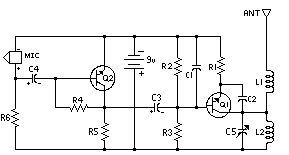
Simple FM transmitter with 2N3904

simple FM transmitter
In this section discuss about the series of mini fm transmitter, with broadcast coverage of about 300-400 meters. when using a 9 volt working voltage, the transmit power of about 300 meters and when using the working voltage 12 volts, the range of about 400-450 meters, depending on the antenna you use.

This scheme of simple fm transmitter
simple FM transmitter

For L1 and L2 windings 5 times the wrap, you can use a pen to fill melilitnya so neat and after lepaslah content of these pens. C5 is used for placement of broadcasting frequencies, can be tuned between 88-108 mhz, to reach further use steering antenna or Yagi antenna.

Part List
C1 = 0.001uF
C2 = 5.6pF
C3 = 10uF
C4 = 10uF
C5 = 3 - 18pF Adjustable capacitor
R1 = 270R
R2 = 4.7K
R3 = 10K
R4 = 100K
R5 = 4.7K
R6 = 4.7K
Q1 = 2N2222A
Q2 = 2N3904
L1 = 5 turn
L2 = 5 turn
Continue Reading..