Saturday, January 11, 2014

4 X 15 Watt Mini Power Amplifier

A lot of electronic circuits in the domain of audio amplifiers are already been published here. This circuit is a little different because it is a four channel amplifier. Each channel of this amplifier can deliver an output of 15Watts into a 4 ohm speaker. The amplifier can be operated from a single 12V DC supply and this makes it possible to use this amplifier in car audio applications too.

4 X 15 Watt Mini Power Amplifier Circuit diagram :
4X15W-amplifier-circuit Diagram

The circuit is based on the 15W BTL X 2 channel audio power amplifier IC TA8215 from Toshiba. Even though chip is specifically designed for car audio applications it can be also used for home audio applications. Two TA8215 ICs are used here in order to obtain a 4 channel amplifier system. The circuit is designed almost exactly as per the application diagram in the ICs datasheet. Pins 7 and 19 are the Vcc pins of the ICs internal integrated power amplifier stages and these pins are connected to the positive supply. Pin 9 is the Vcc pin for ICs internal preamplifier and it is also connected to the positive supply. Pins 13 and 14 are the internal power amplifiers ground pins and they are tied together and connected to the ground.
The internal preamplifier’s ground pin (pin5) is connected to the common ground through a 10 Ohm resistor which makes the input ground separated from the common ground by a resistance of 10 ohms and this improves the noise rejection. The 100uF capacitor works as a power supply de-coupler. The resistor networks connected to the output lines of each amplifier improves the high frequency stability. The variable resistors (R3, R4, R12 and R13) works as the volume controller for the corresponding channels.

Notes :
  • Assembling the circuit on a good quality PCB is a must for obtaining optimum sound quality.
  • Use 12V DC for powering the circuit.
  • The ICs must be fitted with adequately sized heat sinks.
  • R3, R4, R12 and R13 serves as volume controllers.
  • K1 to K4 can be 4 Ohm, 20W speakers.
  • This amplifier circuit can be used in a variety of applications such as car audio systems, home theater systems, personal audio systems, public address systems etc.
Source : http://www.ecircuitslab.com/2012/08/4-x-15-watt-mini-power-amplifier.html
Continue Reading..

Friday, January 10, 2014

Guitar Amplifier

10W Old-Style ultra-compact Combo, Two inputs - Overdrive - Treble-enhancement
The aim of this design was to reproduce a Combo amplifier of the type very common in the sixties and the seventies of the past century. It is well suited as a guitar amplifier but it will do a good job with any kind of electronic musical instrument or microphone. 5W power output was a common feature of these widespread devices due to the general adoption of a class A single-tube output stage (see the Vox AC-4 model). Furthermore, nowadays we can do without the old-fashioned Vib-Trem feature frequently included in those designs. The present circuit can deliver 10W of output power when driving an 8 Ohm load, or about 18W @ 4 Ohm. It also features a two-FET preamplifier, two inputs with different sensitivity, a treble-cut control and an optional switch allowing overdrive or powerful treble-enhancement.

Guitar Amplifier Circuit Diagram

Guitar Amplifier Circuit Diagram

Parts:
P1______________4K7 Linear Potentiometer
P2_____________10K Log. Potentiometer
R1,R2__________68K 1/4W Resistors
R3____________220K 1/4W Resistor
R4,R6,R11_______4K7 1/4W Resistors
R5_____________27K 1/4W Resistor
R7______________1K 1/4W Resistor
R8______________3K3 1/2W Resistor
R9______________2K 1/2W Trimmer Cermet
R10___________470R 1/4W Resistor
R12_____________1K5 1/4W Resistor
R13___________470K 1/4W Resistor
R14____________33K 1/4W Resistor
C1____________100pF 63V Ceramic Capacitor
C2____________100nF 63V Polyester Capacitor
C3____________470µF 35V Electrolytic Capacitor
C4____________220nF 63V Polyester Capacitor (Optional, see Notes)
C5_____________47µF 25V Electrolytic Capacitor (Optional, see Notes)
C6______________1µF 63V Polyester Capacitor
C7,C8,C9,C10___47µF 25V Electrolytic Capacitors
C11____________47pF 63V Ceramic Capacitor
C12__________1000µF 35V Electrolytic Capacitor
C13__________2200µF 35V Electrolytic Capacitor
D1_____________5mm. Red LED
D2,D3________1N4004 400V 1A Diodes
Q1,Q2________2N3819 General-purpose N-Channel FETs
Q3____________BC182 50V 200mA NPN Transistor
Q4____________BD135 45V 1.5A NPN Transistor (See Notes)
Q5____________BDX53A 60V 8A NPN Darlington Transistor
Q6____________BDX54A 60V 8A PNP Darlington Transistor
J1,J2________6.3mm. Mono Jack sockets
SW1____________1 pole 3 ways rotary switch (Optional, see Notes)
SW2____________SPST Mains switch
F1_____________1.6A Fuse with socket
T1_____________220V Primary, 48V Center-tapped Secondary 20 to 30VA Mains transformer
PL1____________Male Mains plug
SPKR___________One or more speakers wired in series or in parallel, Total resulting impedance: 8 or 4 Ohm, Minimum power handling: 20W
Notes:
  • SW1 and related capacitors C4 & C5 are optional.
  • When SW1 slider is connected to C5 the overdrive feature is enabled.
  • When SW1 slider is connected to C4 the treble-enhancer is enabled.
  • C4 value can be varied from 100nF to 470nF to suit your treble-enhancement preferences.
  • In all cases where Darlington transistors are used as the output devices it is essential that the sensing transistor (Q4) should be in as close thermal contact with the output transistors as possible. Therefore a TO126-case transistor type was chosen for easy bolting on the heatsink, very close to the output pair.
  • To set quiescent current, remove temporarily the Fuse F1 and insert the probes of an Avo-meter in the two leads of the fuse holder.
  • Set the volume control to the minimum and Trimmer R9 to its minimum resistance.
  • Power-on the circuit and adjust R9 to read a current drawing of about 25 to 30mA.
  • Wait about 15 minutes, watch if the current is varying and readjust if necessary.
Technical data are quite impressive for so simple a design:
Sensitivity:
30mV input for 10W output
Frequency response:
40 to 20KHz -1dB
Total harmonic distortion @ 1KHz and 10KHz, 8 Ohm load:
below 0.05% @ 1W, 0.08% @ 3.5W, 0.15% at the onset of clipping (about 10W).

Source :  http://www.ecircuitslab.com/2011/05/guitar-amplifier-circuit-diagram.html
Continue Reading..

Other important factors to be considered

Other important factors to be considered are the Settling time and ringing and the Stability Factors.
In the field of electronics, amplifiers and their performance play a key role in any audio-visual equipment. The best systems will be judged only by the quality of their sound output. Some of the following points can help you to make up your mind. The Power Rating indicates the power of the amplification. You can buy one amplifier for all the speakers or you can have an amplifier for each speaker. Amplifiers also perform cross- over functions. You can assign high frequencies to one set of speakers and low frequencies to another set.
Equalizer is a programme that controls frequencies of signals by mixing channels. This can be programmed until you get the output that suits your ears. Choose an amplifier that has the least distortion factor. The above pointers ought to help you buy am amplifier that helps you enjoy high fidelity music at home or in your car without any distortion.Amplifiers are essentials not just for electric musical instruments, but for a whole slew of other devices including cars, radios, videos, transistors, and so on. Essentially, an amplifier is any device that increases the output signal of another device. The most common kind of amplifier for sale is the kind used in music or speech devices. This category also has many different kinds, so get to know whats out there before you make your purchase.An amplifier will be a great add on to your instrument or sound system because it will improve the volume and quality of the sound produced. In cases such as performances, or even just watching a much-awaited movie on DVD, having great, maximum sound output is necessary.
Smaller speakers should also be set up to get the frequencies they need. If amplified, these speakers almost always should have a crossover attached to ensure that big bass tones wont damage the speakers designed for midrange response and high frequencies. Dividing the sound into low, middle and high frequencies using the different types of speakers creates a medley of tuned sound that gives the experience we want from our systems.
Pay attention to ohms and power ratings, and be sure to match all accordingly.
Continue Reading..

Simplest Intercom

This circuit was requested by an school teacher. It is a simple intercom that anyone can put together and get to work. It is based on the LM380 IC chip. This chip is able to put out 2 watts of power if it is heat sink properly. The following pins should be grounded and attached to a foil to dissipate the heat. Pins 3,4,5,10,11,12 should all be grounded. The circuit works as follows. Switch 1 is a double pole double throw switch. In one position is the talk position and in the other is the listen position.

Circuit Diagram

Simplest Intercom circuit diagram

In the diagram shown the switch is in the talk position for the speaker on the left. Talking into the speaker inputs a signal to the IC chip through the matching transformer T1. The output from the IC chip goes to the speaker on the right. If you put the switch in the other position the speaker on the right is the talking unit and the speaker on the left listens. Volume is controlled by the 1meg ohm pot R1. This circuit is very basic but is a good start for a child or anyone starting new in electronics.
Continue Reading..

Friday, December 27, 2013

LA4440 Amplifier Circuit

LA4440 is a dual channel audio amplifier IC. It can be used in two modes; one is Stereo amplifier and another Bridge amplifier mode. The LA4440 is a monolithic linear IC from Sanyo. Here I give the both circuit mode of amplifier using IC LA4440.

Features of IC LA4440

  • It has 46dB of ripple rejection
  • Low distortion
  • Good channel separation
  • Thermal protector
  • Overvoltage protector
  • Surge voltage protector

LA4440 Stereo Amplifier Circuit

When the IC LA4440 is Stereo mode in the circuit, its output power is 6w+6w. In stereo mode use two pieces speaker of 2Ωto8Ω.
In the stereo amplifier configuration given below, C11 and C12 are output capacitor. But i ignore them from the circuit of bridge amplifier.

Stereo Amplifier Circuit using IC LA4440
Fig-1: LA4440 Stereo Amplifier Circuit Diagram

LA4440 Bridge Amplifier Circuit

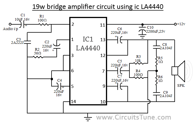
When the IC LA4440 is in Bridge mode in the circuit, its output power is 19w. In bridge mode use 4Ω-8Ω speaker. If you want stereo output(19w+19w) in bridge mode then use two copies of amplifier circuit of given below. Resistor R3&R4 is to adjust the voltage gain and for making input signal of inverting amplifier.

Bridge Amplifier Circuit using  IC LA4440
Fig-2: LA4440 Bridge Amplifier Circuit Diagram

Circuit description for both, stereo and bridge amplifier mode


C10 is filter capacitor used to reduce the ripple of supply voltage. Don’t decrease the value of capacitor C6&C7 less than 100uF, 10v, it may causes of the output at low frequencies goes lower. The pin-6 of LA4440 amplifier circuit  is audio input pin; it used in stereo amplifier mode but in bridge mode it is grounded. C8&C9 are polyester film capacitor used to preventing oscillation, and R1&R2 used for the same reason as filter resistor. Though the maximum supply voltage for both circuit of amplifier is 18V but we recommend to use a 12V,3A power supply. Use a good quality heat sink with LA4440.

I think here you see little comparison between stereo and bridge amplifier of LA4440. If you want to make this amplifier project, then I recommend you the bridge one. I think it is ideal for a beginner. And I love its wattage rather than Stereo mode. There is also a possibilities as I say, make two copies of circuit of bridge amplifier for stereo, it will give you 19w+19w of audio power output.
Continue Reading..