Two or more alternators may be operated in parallel, with each alternator carrying the same share of the load. However, certain precautions must be taken and various conditions complied with before connecting an alternator to a bus with another alternator.
Synchronizing, or paralleling, alternators is somewhat similar to paralleling dc generators, except that there are more steps with alternators.
In order to synchronize (parallel) two or more alternators to the same bus, they must have the same phase sequence as well as equal voltages and frequencies. The following steps are a general guide in synchronizing an alternator and connecting it to a bus system on which one or more alternators are already operating.
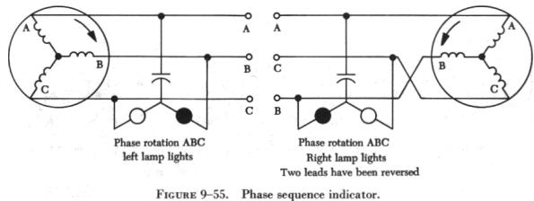
1. Phase sequence check. The standard phase sequence for ac, three phase power circuits is A, B, C. The phase sequence can be determined by observing two small indicator lamps, connected as shown in figure 9-55. If one lamp lights, the phase sequence is A, B, C. If the other lamp lights, the phase sequence is A, C, B. If the light indicates the wrong phase sequence, reverse the two leads to the incoming alternator. To parallel or synchronize two alternators with the wrong phase sequence would be the same as short circuiting two leads and would set up dangerous circulating currents and magnetic disturbances within the alternator system, which could overheat the conductors and loosen the coil windings.
2. Voltage check. The voltage of the alternator to be connected to the bus must be equal to the bus voltage. It is adjusted by a control rheostat located on the switch panel. This rheostat controls the current in the voltage regulator coil and causes the alternator magnetic field to increase or decrease, controlling, in turn, the alternator voltage.
3. Frequency check. The frequency of an alternator is directly proportional to its speed. This means that the speed of the alternator being connected to the bus must equal the speed of the alternators already connected. By observing the frequency meter and by adjusting the rheostat on the switch panel, the frequency of the incoming alternator can be brought up to the correct value. By observing the synchronizing lamp, shown in figure 9-56, and by fine adjustment of the speed control rheostat, the frequencies may be brought to almost exact synchronization. The synchronizing lamp will blink as the two frequencies approach the same value; when they are very nearly the same, the lamp will blink slowly. When the blinking decreases to one blink or less per second, close the circuit breaker while the lamp is dark and connect alternator No. 2 to the bus. The dark lamp indicates no voltage between phase A of the bus and phase A of the incoming alternator. During the period when the lamp is lighted, there is a voltage difference between phase A of the bus and phase A of the alternator to be connected to the bus. To close the circuit breaker when the synchronizing lamp is lighted would be similar to short circuiting two leads and would cause serious voltage and magnetic disturbances within the alternators.
Alternator Protective Circuits
It is very important that operating alternators be disconnected from the system when harmful electrical faults occur. For an alternator to be removed from the bus when trouble occurs in the circuit, circuit breakers must open rapidly and automatically; otherwise, the alternator could burn up. To provide relays in the circuit breakers, there are a number of protective relays in the circuit.
Most of these relays are dc energized, since similar ac equipment is usually much heavier and less efficient.
There are two circuit breakers in this type of airplane alternator control system: (1) The exciter control relay, which opens and closes the exciter field circuits, and (2) the main line circuit breaker, which connects or disconnects the alternator from the bus and also opens or closes the exciter field current.
The main line circuit breaker is latched by a dc electromagnet, called a "close" coil. This coil closes the circuit breakers. They are released by a second electromagnet, known as the trip coil, which opens the circuit. Only momentary contact of the closing and tripping circuits is necessary for operation. Once closed, a mechanical latch holds the contactors until the latch is released by the trip coil. The contacts are made of special alloys capable of breaking currents of several thousand amperes without damage to the contacts.
This main line triple pole circuit breaker has an auxiliary contact which closes the exciter field circuit whenever the main line circuit breakers close and opens it whenever the circuit breakers open. This is desirable because the alternator may be supplying load current when the circuit breakers open; in which case, the exciter field excitation should be decreased or removed. Also, the exciter field circuit is held closed until the main circuit breakers can open, in case the exciter control relay is opened first.
The exciter control relay opens and closes the exciter field circuit. Upon opening, it closes a contact furnishing dc power to the main line trip coil and causes the main line circuit breakers to open. The exciter control relay consists of two solenoids, one latching and one tripping. It needs only momentary closing of the switch for operation.
The exciter ceiling relay is a thermal operated relay. It operates whenever the exciter field current increases enough to be dangerous to the operation of the alternator. If at any time the alternator becomes loaded too heavily, either by a short circuit on the line or by the alternator becoming inoperative, the exciter voltage increases to supply the heavy alternator load, and the thermal ceiling relay closes the contacts between the dc bus and the trip coil. This opens the exciter field and, at the same time, disconnects the alternator from the line.
The differential current protection relay is much simpler in operation than its name indicates. It is designed to protect the alternator from internal shorts between phases or to ground. As long as there is the same amount of current in each phase going into the alternator as coming out, the differential relay does not operate, no matter how heavy or light these currents may be. However, if a short occurs within the alternator in any one phase, there is a difference in current through the lines; the relay operates, closing the circuit t the exciter trip coil, which, in turn, closes the circuit to the trip coil of the main line circuit breakers. T
The two leads from each phase of the alternator are passed through the doughnut-like holes in the relay and act as the primaries of the current transformers. As the current flows in opposite directions in the two leads through each hole, their magnetic fields are canceled and no current flows in the current transformer secondary, which energizes the relay. The relay does not operate until a fault occurs that unbalances the currents in these two conductors and causes current to flow in the current transformer secondary. Failure of the differential current relay would be backed up by the exciter protection relay. Fast clearing of internal faults reduces danger from fire and also reduces system disturbances when the alternators are paralleled improperly. A time delay action in the exciter protection relay allows overexcitation for short intervals in order to supply dc voltage for clearing faults and for brief demands for current beyond the capacity of the alternator. It also opens the main breaker and drops the alternator excitation when other protective devices fail.