Friday, December 27, 2013

LA4440 Amplifier Circuit

LA4440 is a dual channel audio amplifier IC. It can be used in two modes; one is Stereo amplifier and another Bridge amplifier mode. The LA4440 is a monolithic linear IC from Sanyo. Here I give the both circuit mode of amplifier using IC LA4440.

Features of IC LA4440

  • It has 46dB of ripple rejection
  • Low distortion
  • Good channel separation
  • Thermal protector
  • Overvoltage protector
  • Surge voltage protector

LA4440 Stereo Amplifier Circuit

When the IC LA4440 is Stereo mode in the circuit, its output power is 6w+6w. In stereo mode use two pieces speaker of 2Ωto8Ω.
In the stereo amplifier configuration given below, C11 and C12 are output capacitor. But i ignore them from the circuit of bridge amplifier.

Stereo Amplifier Circuit using IC LA4440
Fig-1: LA4440 Stereo Amplifier Circuit Diagram

LA4440 Bridge Amplifier Circuit

When the IC LA4440 is in Bridge mode in the circuit, its output power is 19w. In bridge mode use 4Ω-8Ω speaker. If you want stereo output(19w+19w) in bridge mode then use two copies of amplifier circuit of given below. Resistor R3&R4 is to adjust the voltage gain and for making input signal of inverting amplifier.

Bridge Amplifier Circuit using  IC LA4440
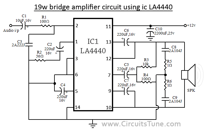
Fig-2: LA4440 Bridge Amplifier Circuit Diagram

Circuit description for both, stereo and bridge amplifier mode


C10 is filter capacitor used to reduce the ripple of supply voltage. Don’t decrease the value of capacitor C6&C7 less than 100uF, 10v, it may causes of the output at low frequencies goes lower. The pin-6 of LA4440 amplifier circuit  is audio input pin; it used in stereo amplifier mode but in bridge mode it is grounded. C8&C9 are polyester film capacitor used to preventing oscillation, and R1&R2 used for the same reason as filter resistor. Though the maximum supply voltage for both circuit of amplifier is 18V but we recommend to use a 12V,3A power supply. Use a good quality heat sink with LA4440.

I think here you see little comparison between stereo and bridge amplifier of LA4440. If you want to make this amplifier project, then I recommend you the bridge one. I think it is ideal for a beginner. And I love its wattage rather than Stereo mode. There is also a possibilities as I say, make two copies of circuit of bridge amplifier for stereo, it will give you 19w+19w of audio power output.
Continue Reading..

Thursday, December 26, 2013

This can also expand the brand mobile phone manufacturers

cell phone jammer can help the school prevent students against using the cell phone in the improper time.
Recycling of electronic products under the generally applicable "producer responsibility" principle, responsible for waste recycling mobile phones and other electronic products, primarily responsible for the use of the mobile phone manufacturer, that manufacturer should be used mobile phones and other electronic products recycling and utilization of play a major role. Major brand mobile phone manufacturers should set up a special cell phone recycling organization will be incorporated into the service of mobile phone recycling. Can be recycled to the cell phone repair and renovation of the old channels after the regular sale to economically underdeveloped areas, to expand sales of mobile phone market. This can also expand the brand mobile phone manufacturers, mobile phone manufacturers such behavior will be recognized by consumers. For businesses, reputation is an intangible asset. The most important thing is good publicity, so that users know that mobile phones and other electronic products recycling pathway. Can hold a number of recycling activities can enhance the users participation in environmental awareness. Innovation and recovery, so that people in the process of recycling used batteries to get a sense of psychological pleasure; paid recycling, so that people get the corresponding labor compensation; publicity and education so that people value their sense of identity recovery behavior. However, the low return rate for disposal of batteries, long cycle efficiency, it is difficult to attract investors, so it is difficult to form industrial scale, and produce benefits. In fact, used cell phone battery recycling industry is not profitable. Contains a large number of used cell phone batteries can be recycled such as heavy metals and acid substances, such as lead-acid battery recycling mainly recycling of lead-based waste, but also for the use of waste acid and plastic casing.  With the popularity of mobile phones, used cell phone batteries have become a special type of e-waste, the current cell phone batteries are Cd-Ni, MH-Ni and Li-ion three types of batteries, Cd-Ni battery is the main pollutants Ni, Cd and KOH, nickel-metal hydride battery is the main pollutants Cd, Cu and KOH, lithium-ion battery is the main pollutant Co, Mn and organic electrolytes. The resulting environmental pollution and waste of resources has become increasingly prominent. Used cell phone batteries on the environment and human health hazards mainly from the one containing the acid, alkali and heavy metals such as electrolyte solution. At present, China is mainly used mobile phone batteries with household waste in landfills, incineration, composting and other methods for processing, and waste batteries if the joint deal with the garbage man will be brought to the environment and great potential harm.
Continue Reading..

Pulse Charger for Reviving Tired Lead Acid Batteries

If you own a motorcycle, a motor home, a caravan, a lawn mover, a day cruiser or maybe a vintage car you must at some point had to write off a lead acid battery. When a battery is improperly charged or allowed to self-discharge as occurs during non-use, sulphate crystals build up on the batterys plates. The sulphate preventing the battery from being fully charged and therefore it is unable to deliver its full capacity. When trying to charge a battery in this state it only gets hot and looses water, the gravity of the electrolyte is not increasing to its normal “full charge” state. The only thing you do is killing the battery completely. If a battery has a resting voltage of at least 1.8 Volts/cell and no cells are shorted, desulphation of its plates can be done. This circuit is an add-on and part for a modification of a normal charger and it takes care of the sulphate problem.

Pulse Charger for Reviving Tired Lead Acid Batteries Circuit diagram:

Pulse Charger for Reviving Tired-Lead Acid Batteries-Circuit diagram

CAUTION:

Before you begin a project like this remember: mains voltage is dangerous so if you are not 100% sure of what you’re doing consult a friend who has the skills or, don’t do it at all !

The project: get hold of an old charger, big or small it’s your choice depending on the size of batteries you normally handle (bigger is better). There are some tricks to boost the performance if you need it. Start by ripping out everything except the transformer and the rectifier. Some older chargers are equipped with fin rectifiers, which have high voltage drop and must be replaced. Replace with a rugged bridge rectifier that can cope with the amperes. All wiring on secondary should be short and heavy wire. The rectifier should be bolted to the chassis to keep cool. If the charger have a high/low switch it’s a bonus, if not you can in some cases add a few turns of wire on the secondary winding. The circuit; a 14-stage ripple counter and oscillator IC 4060 produce a pulse, which is the heartbeat of the circuit. The pulse is feed to the 555 timer that deicide the length of the active output. With the switch you can select long or short pulse output. The output of the 555 timer triggers the zero-cross optoisolator triac driver MOC 3041 via a transistor. This gives the charger transformer a soft start via the triac and the snubber circuit. A small power supply is necessary for the circuit and consists of T1 a transformer 15V 0.1A secondary, a bridge rectifier, a regulator and two caps. Because this project include a charger that is (X) the outcome can differ in performance from one case to another. However this do not mean that your project doesn’t work, but the efficiency can vary. Some notes the snubbercap is a high voltage AC type (X) and the resistors on the mains side is at least 0.5W type. Use a triac that can take 400V+ and 10A+, I use BTA 25.600 but this is overkill in most cases. No PCB sorry!

How it works:

Well the short version. The object is to get the cell voltage high enough for the sulphate to dissolve without boiling or melting the battery. This is achieved by applying higher voltage for shorter periods and let the battery rest for a while. The pulses on short range is about 0.5s on / 3s off and the long pulse range is 1.4s on / 2s off. These times can vary depending on component tolerances. Start on long pulse and if you discover “boiling” (more than with normal charging) in the electrolyte switch to short puls. Don’t leave the process unattended, at least until you know how your specific version of this project turns out. I built ver.1 of this circuit some 10 years ago and have experimented with it but I’m sure someone can improve it further.

Good Luck! Ante
Ante135@hotmail.com

Continue Reading..

Tuesday, December 24, 2013

Cable Tester

This cable tester allows you to quickly check audio cables for broken wires. Because of the low power supply voltage, batteries can be used which makes the circuit portable, and therefore can be used on location.

Cable Tester Circuit diagram:

Simple Cable Tester-Circuit Diagram

The design is very simple and well organ-ised: using the rotary switch, you select which conductor in the cable to test. The corresponding LED will light up as indication of the selected conductor. This is also an indication that the power supply volt-age is present. If there is a break in the cable, or a loose connection, a second LED will light up, corresponding to the selected conductor. You can also see immediately if there is an internal short circuit when other than the corresponding LEDs light up as well.

You can also test adapter and splitter cables because of the presence of the different connectors.
Two standard AA- or AAA- batteries are sufficient for the power supply. It is recommended to use good, low-current type LEDs. It is also a good idea not to use the cheapest brand of connectors, otherwise there can be doubt as to the location of the fault. Is it the cable or the connector.

Source:   http://www.ecircuitslab.com/2012/06/simple-cable-tester.html
Continue Reading..

Monday, December 23, 2013

New Automatic Shutoff Battery Charger Circuit Diagram

This is a New Automatic Shutoff Battery Charger Circuit Diagram. This automatic shutoff battery charger circuit diagram Adjust by setting the 500 ohm resistor while attached to a fully charged battery.

New Automatic Shutoff Battery Charger Circuit Diagram

New Automatic Shutoff Battery Charger Circuit Diagram

Continue Reading..

Saturday, December 21, 2013

The security is installing cell phone jammer in the hall

The security is installing cell phone jammer in the hall
Store the device in cold areas, when the cell phone temperature, moisture can form inside cell phone circuit board caused by the destruction. A cell phone the other is not being used next to the program-controlled telecell phones: Avoid next to are using a program-controlled telecell phone using the GSM cell phone, GSM cell phone with the program-controlled telecell phone interference greatly, as well as the two sides could not hear. Note Save the cell phone and its components: Do not drop, knock, or shake the device, Rough handling can break internal circuit boards. Note that usually your cell phone and its parts, and accessories out of childrens reach, to prevent accidents caused by damage to the cell phone. You can buy a holster, usually to put a protective clothing. Never use harsh chemicals, cleaning solvents or strong detergents to clean the cell phone. Clear internal screen dust: to prepare a roll of sealing a wide paper tape, the single piece of adhesive tape attached to the machines internal display on the reverse shell inside the shell, attach a snapping compaction, remove tape paper, assembly machines.
To enter the Cell phone Wizard - File Manager - Enter the password (if not change your password is the default 123) - to find the encrypted file - Options - Encryption (more than one file is encrypted, the first tag, and then encryption). Cell phone Wizard can only encrypt files, and does not encrypt the folder, can see the encrypted file, Y-or Q-Manager, a can not be opened ... just go to the cell phone wizard decrypt file management, and point option selected decryption can. Encrypted using a cell phone lock. Starting a cell phone lock will open the file the program locks, there is no password to open this program, so as to achieve the purpose of the encrypted file.
A: officesuite can view and edit TXT file, is: Whether you TXT file in which folder to find the file open, direct calls officesuite. DOC document procedures, You can view and edit, save still saved in the original location. So that we can COPY from the computer text file into our cell phone spare. (Note: the installed officesuite was click on the TXT file with "Notepad" program to open the cell phone, stored in a directory on the Notepad, and now can not be used Notepad to open the, unless you have a text file in the directory on the Notepad) to question 26, why can not find my 100 access to audio-visual cell phones UMD and TXT e-book?As follows: right click on the program, select Properties, select the compatibility 2000 compatibility mode.
Continue Reading..

Friday, December 20, 2013

100W Inverter Schematic

Here is a 100 Watt inverter circuit using minimum number of components. I think it is quite difficult to make a decent one like this with further less components.Here we use CD 4047 IC from Texas Instruments for generating the 100 Hz pulses and four 2N3055 transistors for driving the load. The IC1 Cd4047 wired as an astable multivibrator produces two 180 degree out of phase 100 Hz pulse trains.

These pulse trains are preamplified by the two TIP122 transistors.The out puts of the TIP 122 transistors are amplified by four 2N3055 transistors (two transistors for each half cycle) to drive the inverter transformer.The 220V AC will be available at the secondary of the transformer. Nothing complex just the elementary inverter principle and the circuit works great for small loads like a few bulbs or fans.If you need just a low cost inverter in the region of 100 W, then this is the best.

 100 Watt Inverter Circuit diagram:

100watt  inverter circuit schematic diagram
Parts:
P1 = 250K
R1 = 4.7K
R2 = 4.7K
R3 = 0.1R-5W
R4 = 0.1R-5W
R5 = 0.1R-5W
R6 = 0.1R-5W
C1 = 0.022uF
C2 = 220uF-25V
D1 = BY127
D2 = 9.1V Zener
Q1 = TIP122
Q2 = TIP122
Q3 = 2N3055
Q4 = 2N3055
Q5 = 2N3055
Q6 = 2N3055
F1 = 10A Fuse
IC1 = CD4047
T1 = 12-0-12V
Transformr Connected in Reverse
Notes:
  • A 12 V car battery can be used as the 12V source.
  • Use the POT R1 to set the output frequency to50Hz.
  • For the transformer get a 12-0-12 V , 10A step down transformer.But here the 12-
  • 0-12 V winding will be the primary and 220V winding will be the secondary.
  • If you could not get a 10A rated transformer , don’t worry a 5A one will be just
  • enough. But the allowed out put power will be reduced to 60W.
  • Use a 10 A fuse in series with the battery as shown in circuit.
  • Mount the IC on a IC holder.
  • Remember,this circuit is nothing when compared to advanced PWM
  • inverters.This is a low cost circuit meant for low scale applications.
Design tips:
  1. The maximum allowed output power of an inverter depends on two factors.The
  2. maximum current rating of the transformer primary and the current rating of the driving
  3. transistors.
  4. For example ,to get a 100 Watt output using 12 V car battery the primary current will be
  5. ~8A ,(100/12) because P=VxI.So the primary of transformer must be rated above 8A.
  6. Also here ,each final driver transistors must be rated above 4A. Here two will be
  7. conducting parallel in each half cycle, so I=8/2 = 4A .
  8. These are only rough calculations and enough for this circuit.
Source :   http://www.ecircuitslab.com/2011/06/100w-inverter-circuit-diagram-schematic.html
Continue Reading..

Thursday, December 19, 2013

Multi Color LED

How many different conditions do you reckon may be signalled with just one LED? Two, maybe three? Using this simple circuit, a lot more!


Admittedly, a two-colour LED is used here. Such a device consists of two light-emitting chips, usually red and green, encapsulated in the same case. It has three pins: two for the anodes, and one for the common cathode. In this way, each diode can be activated separately. Various mixed colours may be obtained by varying the current through the two diodes. At least four discrete colours are then easily perceived: pure red, pure green, orange (IR ≈ 2IG) and yellow (IG ≈ 2IR).

In the present circuit, the LED elements are driven by CMOS three-state buffers type 4503, which, unlike most CMOS ICs from the 4000 series, are capable of supplying up to 10 mA of output current. The LED cur-rents are limited by resistors R1 through R6, whose values invite experiments with brightness and colours according to your own taste.


Simple Multi-Color LED Circuit diagram:

Simple Multi-Color LED-Circuit Diagram


The circuit was originally developed to indicate the state of three inputs, a, b, and c (non-binary, i. e., only one of these is at 1 at any time), with the con-figuration (a=b=c=0) representing the fourth state. The latter is decoded by NAND gate IC1. An additional effect is produced by gates IC1a and IC1b, which are connected up into an oscillator circuit producing approximately two pulses per second. These pulses are used to control the common-enable input, DA (pin 1) of the 4503, so as to produce a flickering effect. The oscillator is controlled by means of inputs ‘d’ and ‘e’. Pulling both of these logic high disables the oscillator and the LED driver. With e=0 and d=1 the outputs of the 4503 are switched to three-state, and the circuit is in power-down standby mode.

Although designed for a 12-V supply voltage, the circuit will happily work at any supply volt-age between 5 V and 16 V. Non-used inputs of CMOS ICs must, of course, be tied to ground via 10-100 kW resistors.

Source: http://www.ecircuitslab.com/2012/06/simple-multi-color-led.html
Continue Reading..

Wednesday, December 18, 2013

Telephone line Based Audio Muting and Light On

Very often when enjoying music or watching TV at high audio level, we may not be able to hear a telephone ring and thus miss an important incoming phone call. To overcome this situation, the circuit presented here can be used. The circuit would automatically light a bulb on arrival of a telephone ring and simultaneously mute the music system/TV audio for the duration the telephone handset is off-hook. Lighting of the bulb would not only indicate an incoming call but also help in locating the telephone during darkness.

Telephone line Based Audio Muting and Light-On Circuit Diagram

Telephone line Based Audio Muting and Light-On Circuit Diagram
On arrival of a ring, or when the handset is off-hook, the inbuilt transistor of IC1 (opto-coupler) conducts and capacitor C1 gets charged and, in turn, transistor T1 gets forward biased. As a result, transistor T1 conducts, causing energisation of relays RL1, RL2, and RL3. Diode D1 connected in antiparallel to inbuilt diode of IC1, in shunt with resistor R1, provides an easy path for AC current and helps in limiting the voltage across inbuilt diode to a safe value during the ringing. (The RMS value of ring voltage lies between 70 and 90 volts RMS.) Capacitor C1 maintains necessary voltage for continuously forward biasing  transistor T1 so that the relays are not energised during the negative half cycles and off-period of ring signal. Once the handset is picked up, the relays will still remain energised because of low impedance DC path available (via cradle switch and handset) for the in-built diode of IC1.

After completion of call when handset is placed back on its cradle, the low-impedance path through handset is no more available and thus relays RL1 through RL3 are deactivated. As shown in the figure, the energised relay RL1 switches on the light, while energisation of relay RL2 causes the path of TV speaker lead to be opened. (For dual-speaker TV, replace relay RL2 with a DPDT relay of 6V, 200 ohm.) Similarly, energisation of DPDT relay RL3 opens the leads going to the speakers and thus mutes both audio speakers. Use ‘NC’ contacts of relay RL3 in series with speakers of music system and ‘NC’ contacts of RL2 in series with TV speaker. Use  ‘NO’ con-tact of relay RL1 in series with a bulb to get the visual indication.

Source: http://www.ecircuitslab.com/2011/12/telephone-line-based-audio-muting-and.html


Continue Reading..

Tuesday, December 17, 2013

Video Isolator

These days many more audio-visual devices in the home are connected together. This is especially the case with the TV, which may be connected to a DVD player, a hard disk recorder, a surround-sound receiver and often a PC as well. This often creates a problem when earth loops are created in the shielding of the video cables, which may cause hum and other interference. The surround-sound receiver contains a tuner that takes its signal from a central aerial distribution system. The TV is also connected to this and it’s highly likely that the PC has a TV-card, which again is connected to the same system. On top of this, there are many analogue connections between these devices, such as audio cables. The usual result of this is that there will be a hum in the audio installation, but in some cases you may also see interference on the TV screen.

The ground loop problem can be overcome by galvanically isolating the video connections, for example at the aerial inputs of the surround-sound receiver and the TV. Special adaptors or filters are sold for this purpose, known as video ground loop isolators. Good news: such a filter can also be easily made at home by yourself. There are two ways in which you can create galvanic isolation in a TV cable. The first is to use an isolating transformer with two separate windings. The other is to use two coupling capacitors in series with the cable. The latter method is easily the simplest to implement and generally works well enough in practice. The simplest way to produce such a ‘filter’ is as an in-line adapter, so you can just plug it onto either end of a TV aerial cable.

Video Isolator Circuit diagram:


The only requirements are a male and female coax plug and two capacitors. The latter have to be suitable for high-frequency applications, such as ceramic or MKT types. It is furthermore advisable to choose types rated for high voltages (400 V), since the voltages across these capacitors can be higher than you might expect (A PC that isn’t connected to the mains Earth can have a voltage as high as 115 V (but at a very low, safe current), caused by the filter capacitors in its power supply. These capacitors don’t need to be high value ones, since they only have to pass through frequencies above about 50 MHz. Values of 1 nF or 2.2 nF are therefore sufficient. To make the isolator you should connect one capacitor between the two earth connections of the coax plugs and the other between the two signal connections.

The mechanical construction has to be sturdy enough such that the connections to the capacitors won’t break whenever the inline adapter is removed forcibly. A good way to do this is to make a cover from a piece of PVC piping for the central part. Wrap aluminium foil round the outside and connect it to one of the plugs, so that the internal parts are properly shielded from external interference. Make sure that the aluminium foil doesn’t make contact with the other plug, otherwise you lose the isolation. The majority of earth loops will disappear when you connect these filters to all used outputs of the central aerial distribution system where the signal enters the house.
Harry Baggen
 
Copyright : Elektor Electronics 2008

Source:http://www.ecircuitslab.com/2011/07/video-isolator-circuit-diagram.html
Continue Reading..

Monday, December 16, 2013

Switching inverter for 12v systems circuit diagram

This PWM control circuit provides the control pulse to the DMOS Power Switch in the flyback circuit. The output of the PWM is a pulse whose width is proportional to the input control voltage and whose repetition rate is determined by an external clock signal. 

To provide the control input to the PWM and to prevent the output voltage from soaring or sagging as the load changes the error amplifier and reference voltage complete the design. They act as the feedback loop in this control circuit much like that of a servo control system.


Switching inverter for 12v systems circuit diagram

Switching inverter for 12v systems circuit diagram

Continue Reading..